



Description
Microdyne 1100-AR(01) Telemetry Receiver Rackmount Chassis RF FM 115VAC 50-400Hz
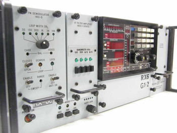
The Microdyne Corporation 1100-AR(01) is a rackmount RF/FM telemetry receiver chassis. The unit houses the main receiver electronics including superheterodyne downconversion circuitry, demodulation stages, and signal-processing subassemblies in an aluminum rackmount enclosure. Internal circuit boards, wiring harnesses, and sub-chassis assemblies are present and intact; however, some front-panel plug-in module slots and card bays appear unfilled, indicating this chassis is incomplete or was configured for partial use. The front panel carries the full complement of operator controls for a configured 1100-AR receiver.
Specifications & What's Included
- Manufacturer: Microdyne Corporation
- Model: 1100-AR(01)
- Serial Number: 2659 (from data plate)
- Type: RF/FM Telemetry Receiver — rackmount chassis
- Power Input: 115VAC, 50–400Hz (per rear panel label)
- Form Factor: Rackmount (aluminum chassis with rack handles)
- Front Panel Controls: PWR OFF/ON, PRE/REC/BAL mode switches, Audio Gain/Operate Mode, Video Source/Video Coupling, Video Bandwidth (KHz), Fine Tune, Auto Search, Search Range
- Front Panel Switches: 1ST LO MODE / 2ND LO MODE selector; XTAL / OFF / VCO / FM / AFC mode switch
- Front Panel Meters: CAL, AN BAL, CARR IND (Carrier Indicator), THRESHOLD, ZERO analog meter displays
- Front Panel: Large center bay and additional slot bays — some unfilled (visible in photos)
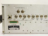
- Rear Panel — RF Input: J2 RF IN (BNC)
- Rear Panel — 1st LO Loop: J3 CUT, J4 IN (BNC)
- Rear Panel — 2nd LO Loop: J5 CUT, J6 IN (BNC)
- Rear Panel — Signal Points: J7 REF CSC CUT, J8 PRE-D REC CUT, J9 PRE-D CONV IN, J10 LTD (BNC connectors)
- Rear Panel — Outputs: 10 MHz OUTPUT (LIN), POLARITY/ZERO/SCALE — Calibrate AGC Record Output, OPTIONAL OUTPUT, PBK IN, VBREC, DISPLAY OUT (BNC connectors)
- Rear Panel — AUX: AUX ACC (CUT/IN), AUX DISPLAY (CUT/IN) connectors
- Rear Panel — Accessories: J1 (D-sub multi-pin)
- Rear Panel — Power: J17 POWER IN (circular multi-pin connector)
- Rear Panel Note: PM ONLY HUMBUCKING / SPARE connector also present
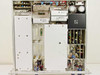
- Internal: Substantial circuitry present — multiple PCB subassemblies, wiring harnesses, card-cage rails; two card slots appear empty
- Chassis only — no external accessories, cables, or plug-in modules confirmed included
Applications
The Microdyne 1100-AR series was a professional-grade telemetry receiver designed for aerospace, military, and test-range applications, particularly for receiving RF downlinks from airborne and missile test vehicles. These receivers were widely deployed at government test ranges, flight test facilities, and satellite ground stations from the 1960s through the 1980s to receive PCM, FM, and analog telemetry data transmitted from aircraft, rockets, drones, and space vehicles during flight test programs. The 1100-AR's dual-conversion superheterodyne architecture, selectable LO modes, and AGC/AFC circuitry made it well suited for tracking fast-moving targets transmitting on IRIG-standard telemetry bands (typically L-band, S-band, or UHF, depending on the configured RF front end). The front-panel video bandwidth and demodulation mode controls allowed operators to configure the receiver for different telemetry subcarrier schemes in real time. Today these units are sought by collectors of vintage aerospace and government test equipment, by historians of Cold War–era flight test programs, and occasionally by engineers supporting legacy telemetry ground stations still in use for older test platforms.
This Microdyne Corporation 1100-AR(01) Telemetry Receiver chassis has been visually inspected and photographed. The chassis contains substantial internal electronics including circuit boards, wiring harnesses, and subassemblies — it is not a bare empty shell. Some front-panel module slots/card bays appear unfilled, as visible in the photos. The unit shows typical wear for vintage rack electronics: light scuffing on the aluminum chassis panels, and the internal wiring and boards are consistent with prior service use. Power requirements are 115VAC, 50–400Hz per the rear panel label. This unit has not been powered up or tested at our facility. Please review all photos carefully and contact us with any questions before purchasing.
Warranty Information
Additional Information
Brand: |
Microdyne |
Model: |
1100-AR(01) |
MPN: |
1100-AR(01) |
SKU: |
39435 |
Type: |
RF/FM Telemetry Receiver Chassis |
Form Factor: |
Rackmount |
Power Requirements: |
115VAC, 50-400Hz |
Receiver Type: |
FM/AM Telemetry Receiver |
Signal Input: |
RF IN (BNC, J2) |
Demodulation Modes: |
FM, AM, PM |
LO Configuration: |
1st LO / 2nd LO selectable |
Frequency Control: |
Fine Tune, Auto Search, XTAL/VCO/AFC modes |
Front Panel Controls: |
Audio Gain, Video BW, Video Source/Coupling, Search Range |
Rear Connectors: |
BNC (RF IN, loop-through), D-sub (Accessories), multi-pin power |
Rear Panel Outputs: |
Pre-D, 10 MHz, Linear, Display Out, Optional Output, PBK In |
AUX Connections: |
AUX ACC (CUT/IN), AUX DISPLAY (CUT/IN) |
Country/Region of Manufacture: |
United States |
Seller Notes: |
Chassis with internal electronics; some front-panel module slots are unfilled. No external accessories included. |
Condition Notes: |
Microdyne 1100-AR(01) Telemetry Receiver chassis with internal electronics present; some front-panel module slots unfilled. Shows typical wear. Not powered or tested at our facility; pulled from prior service use. 115VAC, 50-400Hz. |
California Prop 65 Warning: |
WARNING: This product can expose you to chemicals including lead and lead compounds, and DEHP (a phthalate), which are known to the State of California to cause cancer and birth defects or other reproductive harm. Go to P65Warnings.ca.gov |